Our Products
- Bag Filling Station
- Portable Abrasive Blasting Machine
- CNM MOULDING MACHINES
- BLAST ROOM
- PULSE JET BAG FILTERS
- MULLERS
- LADLES AND LADLE PRE-HEATERS
- MELTING EQUIPMENTS
- OSCILLATING CONVEYOR
- SHOT BLASTING MACHINE VKP SERIES
- SHOT BLASTING MACHINE GG-SERIES
- SAND AERATORS
- MAGNETIC SEPARATOR
- SCREW FEEDERS
- ROTARY TABLE FEEDER
- SAND DRYERS
- POLYGONAL SCREEN
- BUCKET ELEVATORS
- BELT CONVEYORS
- STATIONARY KNOCKOUTS
- SELF DISCHARGE SHAKEOUT
- R-SERIES INTENSIVE SAND MIXER
- CENTRIFUGAL INTENSIVE SAND MIXER
Bag Filling Station
The big bag filling machine has been designed to fill even the most difficult to handle materials,using a time proven technique which involves high precision weighing coupled with a truncated pyramid table with vibrators, the filled material is weighed deaerated and densified before leaving the filling station. The ultimate goal is to produce bags that are stable, stackable, safe & easy to handle.
Empty bags are mounted by hanging the four loops of the bulk bags on the suspended weigh frames easy to reach posts. The inlet spout is secured to the flared end of the filling head by a slip ring seal. The slip ring allows proper positioning of the liner when used. The bag is then inflated and the weight is tared. The electronics has a inbuilt timer- the duration of inflation is time settable.The filling cycle is controlled by the microcontroller for fast and efficient filling. The set points programmed included the target weight, fast/dribble feed, table up / down, no of cycles, vibration on time etc.Once filling and densification is complete the bag’s inlet spout is released from the filling head and tied off. The bulk bag is dismounted from the machine with a fork lift by simply driving under the pallet / bag,lifting it and backing out. The filling system can be complete with a up stream delivery device and the control system.The filling spout is concentric with 2 nozzles for AIR purging & aspiration systems.
Various quantities like 200,500,750 & 1000 kgs can be filled in one cycle
The jumbo bag filling machines are custom designed, the machines can be provided with a roller conveyor underneath, once the filling is complete, the bag is lowered onto the roller conveyor & then the conveyor is switched on & thereby moving the bag out of the machine.
The jumbo bag which is placed on the pallet can be shifted by using a fork lift.
The bag sizes are chosen based on bulk density of the material. Normal bag sizes are
900 x 900 x 1200 mm or 900 x 900 x 1400 mm. the bags are of HDPE material, with plastic liner inside.
Portable Abrasive Blasting Machine
The portable abrasive blaster are safe, high productivity systems designed for use with a wide range of abrasive media. The operation is performed on metals, glass, ceramics, plastic and stone.
The machine works on pressure blasting principle, consist of a blast generator. The abrasives are filled at the top of machine when machine is not working and blast generator is not pressurized. At the top, a vibrating sieve is provided to sieve the abrasive filled. The oversize abrasive and debris are retained on the screen, thus prevent the choking of blast line. When mushroom valve is opened the abrasive will get transferred to blast generator for blasting. The mushroom valve gets closed when compressed air is switched on and abrasive storage tank gets pressurized, for free fall of abrasive into the mixing tube. From mixing tube the abrasive is carried away by compressed air to the nozzle for blasting. The Blast Generator is fabricated from MS Steel plate of thickness not less than 6 mm as per IS-2825 and hydraulically tested for 250 psi.
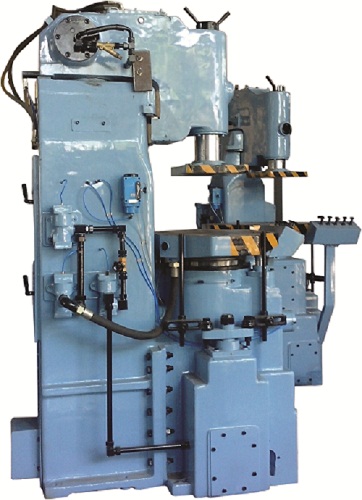
CNM MOULDING MACHINES
Features
- Powerful impact jolting with high dynamic Squeeze force for uniform and rigid moulds.
- Hydro - Pneumatic swing in and out
- Precisely guided pattern draw for damage free striping.
- High Pinlift stroke.
- All Cast parts are S.G. Iron.
Range : Jolt Capacity 300 Kgs to 900 Kgs.
Optionals : Pneumatic or Electro - Pneumatic controls. Pin - Lift or Roller lift mechanism.
Fast, Accurate and Uniform Mould Preparation with Cannery Moulding Machines.
Cannery Moulding Machine is of unique design. It creates the conditions for perfect and uniform moulding properties by high Static Squeeze Force and high Dynamic Squeeze Force. The design fulfills all the requirements for excellent mould quality which is essential for the consistent production of high quality castings. Further they offer technical advantages which are reflected in reduced mould preparation costs.
BLAST ROOM
DESCRIPTION
Blast room is a complete device that can be used for sand blasting of objects of different shapes and sizes. For the process it can be used either metal or mineral abrasive.
Transport of workpieces in the blast room is usually carried out by means of a forklift or on the trolley, usually across the rails. Sand blasting process is carried out by sandblasting pistol, which is directed by the worker on the surface of workpiece. The sandblasting pistol is connected by means of the sandblasting pipe with the pressure vessel, from which the abrasive comes with the compressed air at high speed.
During sandblasting process the worker must be adequately protected with a protective clothes, gloves against the impacts of the abrasive and dust special helmet for head protection.
The blast room housing is rubber-protected. The continuous abrasive returning and cleaning system can have screw conveyors or scraping conveyors applied to the whole shot blasting chamber surface or only part of it. Different platforms for working on heights, devices for spinning rotated treated object around longitudinal axis and abrasive sucking devices provide high work efficiency.
PULSE JET BAG FILTERS
HIGH RATIO PULSE JET BAG FILTERS control particulate emissions and pollution levels. Bag material and air-to-cloth ratio are selected based on application requirements. The bags are supported internally by wire cages which do not impart any load onto the bag. Inspection and maintenance doors are built-in, and platforms and ladders are provided as per requirement. Industries like foundries, cement, mini steel plants, sponge iron plants, power plants, material handling, mining, plastic working, woodworking, and metalworking generate high levels of particulate emissions, which are now closely monitored and regulated by government bodies and legislation.
SEQUENCE OF OPERATION
Dust-laden air enters the unit through the hopper or at the plenum, and clean air flows out of openings in the bag hanging plate. The accumulated dust is removed from outer bag surfaces at regular intervals by short pulses of compressed air introduced into the bag through a solenoid operated pulse valve. A PLC operates the pulse jets in sequence at predetermined intervals. Dust collected in the hopper is discharged through screw conveyors and/or rotary air lock valves. The message is clear — if you want to lower your particulate emissions, our bag filters can do the job for you effectively and reliably. Talk to us today to see how we can help.
OTHER AIR POLLUTION CONTROL EQUIPMENTS: Hopper Vent Filter Scrubber Cyclone Dust Collector Multiclone Dust Collector
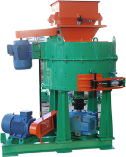
MULLERS
Mullers are primarily designed for mixing green sand for Foundry application. However it finds various other applications like mixing of Abrasives, Battery Paste, Ceramics, Fertilizers, Ore, Food (with some modification), Refractory, Welding Electrode Fluxes etc. The Mullers are available in various sizes – 25 Kg to 1500 Kg batch capacity with respect to Foundry sand.
Mullers are fitted with large mulling rollers for proper needing of the sand as well as two sets of scrapers which move sand from centre to periphery and from periphery centre causing good mixing and pushing sand under the rollers. The 350 Kg and larger Mullers can be provided with Skip hoist for charging of sand and other ingredients. Aerator can also be fitted at the discharge for obtaining fluffy sand as optional extra.
LADLES AND LADLE PRE-HEATERS
Cannery produces treatment ladles as well as pouring ladles for all applications namely Non-Ferrous metals, Iron and Steel. All these ladles are manufactured to high quality standards, generally conforming to Indian Standard Specification or higher, keeping the operational safety as the utmost priority.
SG IRON LADLE:
Both Tundish and Rotary conversion ladles are available for producing SG iron by treatment / inoculation. Rotary conversion ladles uses pure magnesium for this purpose and offers an economic process of production of SG Iron. The Tundish treatment ladle is available from 500 to 2000 Kg and the Rotary conversion ladles from 500 to 1000 Kg capacities.
LIP / TEAPOT SPOUT LADLE:
Both Lip pouring and Teapot spout ladles are meant for Cast Iron. Teapot Spout ladles are used to eliminate the possibility of floating slag getting in to the mould during pouring. The molten metal only from the bottom of the ladle comes through the teapot spout. Worm gear box is provided for easy tilting of the ladle while pouring. These ladles are available from 150 Kg to 16 MT capacities.
BOTTOM POURING LADLE:
Bottom pouring ladles are used for Steel Casting. These ladles are fitted with liver actuated pouring mechanism for easy pouring of molten metal in to the mould cavity. Tilting gear is provided for cleaning purpose. For large crane tilting non-geared ladles common detachable bail arms are provided. These ladles are available from 500 Kg to 25 MT capacities.
MONORAIL TYPE
ladles are equipped with trolley for monorail and hanger having rack and pinion arrangement for easy manipulation during pouring. These ladles are available from 150 Kg to 750 Kg capacities.
LADLE PREHEATER:
Oil or Gas Ladle pre-heaters are used for heating refractory lining of various sizes of lip-pouring and bottom-pouring ladles.
Ladle Preheaters are available in Horizontal or Vertical configuration. Preheating of the ladle refractory lining upto 1000 dec C is possible. Capacities range from 500 kg to 50 MT.
Vertical Preheaters are come with a swilling hood and is preferred for newly lined ladles.
Horizontally fired ladle preheaters, preferred for recycled lades are either stationary or can be moveable on a trolley with rails .
MELTING EQUIPMENTS
CANNERY manufactures a full range Fuel Fired Melting furnaces for Ferrous and Non-Ferrous applications including Copper, Brass, Gunmetal, zinc etc. These furnaces are fired by Oil or Gas or Dual Fuel Wesman make burners.
Range of Oil/Gas fired melting furnaces include the following-
ROTARY FURNACE- capacity rating 300 to 3000 kg batch Cast iron. They are ideal for making heat resisting and other alloyed cast iron castings. Can also be used for melting Brass / Gunmetal, Melting / Smelting of Lead and Aluminium scrap but capacity will vary due to change in density of metal.
SEMI ROTARY FURNACE- capacity 50 kg to 1000 kg of Aluminium Dross. Ideal for recovery of aluminium from aluminium dross.
CRUCIBLE TILTING FURNACE- capacity range is 100 to 1000 Kg Brass / Gunmetal and 30 to 300 kg Aluminium per batch. Due to burner flame not coming in contact with the metal in the crucible, high purity metal and its alloys are suitable for melting in this furnace. These furnaces have central axis manual tilting arrangement with gear mechanism for pouring metal into the ladle. A motorized tilting version with inching facility is also available.
BALE-OUT FURNACE- capacity ranges from 50 to 350 Kg Aluminium and 150 to 1050 Kg Brass / Gunmetal. A cast iron or graphite crucible holds the metal and heating is by the burner firing tangentially around the crucible. Molten metal is bailed out with a spoon for casting small parts.
REVERBERATORY FURNACE- capacity 30 to 5000 kg Aluminium and 90 to 900 kg Brass/Gunmetal. The melting takes place by direct firing of the burner in the furnace chamber and results in efficient and fast heating.
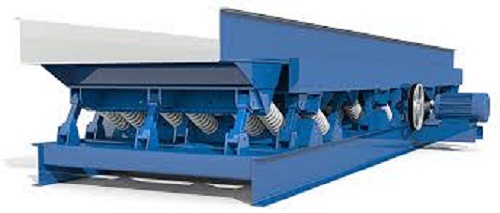
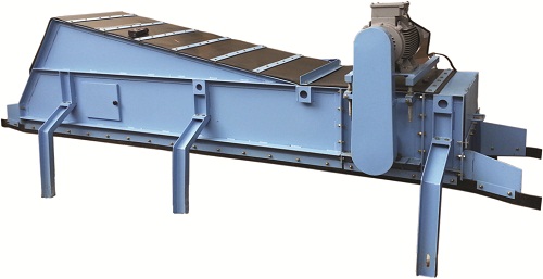
OSCILLATING CONVEYOR
OSCILLATING CONVEYORS are utilized to convey sand or other granular particles at a desired rate. The conveyor is generally placed under a vibrating shakeout or a grid to eliminate direct handling of hot sand by the belt conveyor. In the process of reciprocation, the oscillating conveyor cools the hot sand to some extent which increases the life of the return sand conveyor belt.
CONSTRUCTION
The equipment comprises a metallic trough carried on inclined arms which are fitted with rubber bushes to handle the reciprocating motion of the trough. The oscillating motion of the trough is achieved via specially designed inclined arms and an eccentric shaft driven by a motor through V-belts.
OPERATION
The eccentric shaft is mounted on anti-friction bearings and has V-pulleys at both ends with weights on them to counteract the unbalancing force. The rotation of the eccentric shaft provides a forward and backward motion to a connecting arm attached to the trough through a rubberized pin. A retaining spring assembly at the back of the trough absorbs shock load.
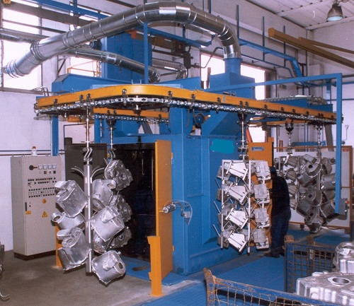
SHOT BLASTING MACHINE VKP SERIES
Discription:
Overhead conveyor shot blasting machine with hook is typically designed to handle mixed loads of medium and large components which often include fragile and sensitive parts that cannot be tumbled in bulk loads. Overhead conveyor shot blasting machines with hook are ideal for heavy and complex shaped work pieces like: casts, welded constructions, forged and pressed parts, remodeled cold or hot and of various complicated forms, steel bottle, springs, etc. Parts can weight from 5 kg to 10,000 kg, manufactured in medium and large series.
This type of shot blasting machines are mostly used for continuous blast cleaning, desanding and decoring in die cast industry as well for descaling, derusting and reconditioning in metalworking industry. Treated objects are hanged individually or in a cluster on revolving hooks on a closed loop conveyor going through the shot blasting machine. In the process of shot-blasting the treated objects revolve and move back and forth in a jet of abrasive media, which provides best possible uniform blasting results.
Overhead conveyor shot blasting machine with hook housing is protected by wear-resistant manganese steel liners or entirely made of manganese steel and additional protection of the most exposed wear areas. High efficiency of the blasting machine is provided by the automatic and continuous abrasive handling and reclamation system for continued returning and cleaning of the shot blasting media, along with efficient blasting wheels made from wear-resistant materials. Standard equipment of larger VKP shot blasting machines includes: PLC, display, timer, automatic or manual mode, pneumatic cylinders on the door, revolving hooks, automatic start-up of throwing wheels, working-hours counter, etc. VKP blasting machine may be equipped with a magnetic separator, vibration conveyor and variable frequency drive for the throwing wheels.
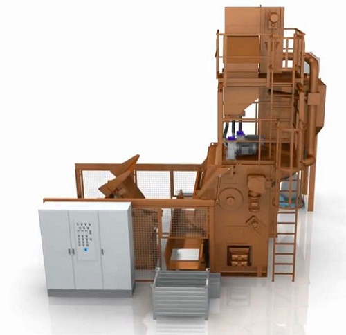
SHOT BLASTING MACHINE GG-SERIES
Discription:
Tumble blast machine with rubber belt is ideal for mass-produced parts, which can be tumbled and will perfectly meet your requirements for batch cleaning, decoring, descaling, deflashing, deburring, and shot peening parts. They are mostly used for process ferrous and non-ferrous castings, forgings and heat treated parts.
Shot blasting machine type GG can be integrated to a fully automatic process with addition of loading and unloading equipment. Tumble blast machines are built in size that can accept single fill / load up to 1,000 kg.
GG blasting machines have a rubber belt conveyor. When the belt moves its special shape causes treated objects to turn and roll, which causes the whole surface of the treated objects to be quality blasted in a jet of abrasive. For emptying the blasting machine, the belt rotation is switched in the opposite direction turning mode. When the blasting machine works in automatic mode the treated objects are loaded into the blasting machine by hydraulic skip loader, tailored to the customer’s specific component containers.
The discharged pieces fall onto vibratory or belt unload channel conveyor and are transported to the next operation. The GG shot blasting machine’s housing is protected by wear-resistant manganese steel liners. High efficiency of the tumble blast machine is enabled by the continuous abrasive handling and reclamations system for continued returning and cleaning of shot blasting media, along with efficient blasting wheels made from wear-resistant materials. Standard equipment of larger tumble blast machines includes: PLC, display, timer, automatic or manual mode, automatic start-up of throwing wheels, working-hours counter, etc. GG shot blasting machine may be equipped with variable frequency drive for the blasting wheels.
SAND AERATORS
Discription:
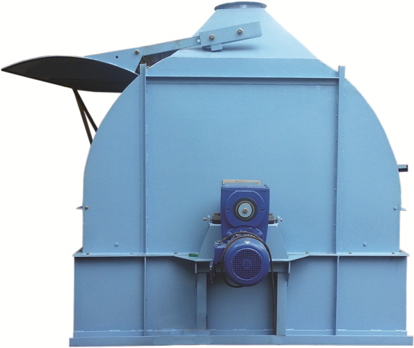
Aerators effectively disintegrate foundry moulding sand to produce fluffy sand that would ram to a uniform density in moulds and produce impression of finer details. Aerators are normally installed at the outlet of Mullers or on top of a distribution belt conveyor after Muller and before molder’s hoppers. Aeration is effected by rotating combs.
MAGNETIC SEPARATOR
OVERBAND PERMANENT MAGNETIC SEPARATOR
The Overband Permanent Magnetic Separator comprises of stationary magnet and a conveyor belt running around the magnet unit to dispose of the attracted iron pieces. The magnet will be of high intensity an iso-trophic Strontium Ferrite Magnet. The magnet unit will be fitted on robustly constructed m.s. frame work to which would be fitted conveyor driving and tension pulleys. The conveyor belt used will be 500 mm wide, 3 ply, grade M-24 with 3 mm top and 1.5 mm bottom covers. The drive will consist of motor coupled to worm reduction gear-box through flexible coupling. Output shaft of the reduction gear will be coupled to conveyor driving head pulley.
SCREW FEEDERS
GENERAL DESCRIPTION AND SPECIFICATION OF SCREW FEEDER
Screw Feeder will consist of a 100 mm to 225mm pitch plate steel helix mounted on a shaft and running in a m.s. fabricated trough. The main components of the feeder will be:
- Trough which will be fabricated from 3 mm thick m.s. sheets. Both ends of the trough will be closed by 6 mm thick m.s. plate covers which will also have bearing blocks mounted on them. Dust seals will be provided in the end covers. The trough with end covers will be mounted on a fabricated frame.
- The top cover for the trough will also be fabricated from 3 mm thich m.s. sheet and fastened to the trough by means of bolts.
- A helicoid flight screw which will be made up of a helix formed from flat steel strip and mounted on a m.s. shaft. The shaft will be partly tubular and partly solid. Solid shaft at both ends will be supported in self sligning ball bearing plummer blocks of C.I. Construction.
- Drive unit will consist of Geared Motor.
ROTARY TABLE FEEDER
GENERAL DESCRIPTION AND SPECIFICATION ROTARY TABLE FEEDER
Rotary Table Feeder will consist of a power driven circulated plate rotating directly below a hopper / bunker. A feed collar located immediately above rotating table used in conjunction with an adjustable plough, determines the volume of material discharged.
The lower edge of the feed collar will be parallel to the table with a predetermined gap from table top. This arrangement permits equal quality of material to flow under the collar and spread over the table as it resolves. The material is then ploughed off into the discharge chute. The plough inside the feed collar.
The major components of the Rotary Table Feeder will be :-
- The table will be fabricated from 12 mm thick m.s. plates and will be mounted on the output shaft of the gearbox. The table will be driven from the output shaft of the reduction gear.
- Adjustable plough assembly.
- Guard ring assembly.
Drive equipment will consist of TEFC sq. cage induction motor coupled through V-belt equipment to the input shaft of a totally enclosed oil imersed worm reduction gearbox. The drive unit will be mounted on a fabricated m.s. base frame.
The Rotary Table feeder will ranges from 5 tons/hr to 30 tons/hr.
SAND DRYERS
Discription:
The supply of sand often contains moisture (unless dried sand is purchased) which is more than what may be used in foundry, especially for core making or for chemically bonded sand system. Therefore, the supplied sand needs to be dried to a known moisture content. Since during drying the sand becomes hot, the same often needs Coolers also so that it can used in the process without without delay.
Sand Drying & Cooling plant complete with equipment for handling and storing of dried and cooled sand. These plants are available from capacities of 3 TPH to 50 TPH. Wesman also supplies individual Dryer and Cooler of smaller sizes – from 200 kg to 5 MT per hour.
If customer prefers we also make and supply customized Rotary Drum drye and Fluidized bed dryer .
When air or gas is passed through a bed of particulate solid material, at a particular range of velocity, the solid bed gets converted into Gas-Solid mixture, expands and the particles move within the bed. At this velocity range the dispersed solid particles acquire many of the properties of a fluid and is said to be in FLUIDISED state. In fluidized state intimate contact between hot gas and solids at high relative velocity enhances heat transfer rates. Thus higher efficiency is obtained due to fluidization. About 30 to 40 % fuel saving is possible in case of Fludised bed dryer compared to Rotary dryer.
Hot air / gas is supplied at a specific pressure in the pressure chamber from which it flows through the distribution plate to the container having the bed of sand to be dried. Hot air may be supplied from oil / gas fired Hot Air Generator (HAG) or an Electric Air Heater. The HAG / Air Heater have been specially designed to operate at relatively high back pressure.
POLYGONAL SCREEN
GENERAL DESCRIPTION OF ROTARY POLYGON SCREEN
The casing of Rotary Polygon Screen will be fabricated from 3 mm thick m.s. sheets suitably reinforced with rolled steel sections. The bottom part of the casing will be rectangular in the shape while the top part will be pentagonal or hexagonal in shape and bolted to the bottom part. Removable panels/doors will be provided in the top part of the casing for inspection purpose. A feeding/receiving chute will be provided at one end of the top part to receive sand from conveyor, elevator or similar feeding device. Provision will be made in the top part of the casing in the form of circular opening for connection to dust extraction system.
The main driving shaft of mild steel will be carried at each end in externally lubricated self aligning ball bearing blocks. Keyed to the shaft will be m.s. or cast iron hexagonal hubs fixed to which will be m.s. radial arms on which will be bolted the frame carrying replaceable wire mesh screen.
Product ranges from capacity of 10 tons/hr to 80tons/hr.
For removal of large pieces of scrap and hard lumps of sand etc. which cannot pass through the wire mesh screen and which travel right through to the end of the screen, suitable reject opening will be provided.
Drive will consist of motor with gearbox . Necessary sheet metal steel guards will be provided over the coupling.
BUCKET ELEVATORS
GENERAL DESCRIPTION AND SPECIFICATION OF CENTRIFUGAL DISCHARGE TYPE BELT & BUCKET ELEVATORS
These specifications apply to centrifugal discharge type belt and bucket elevators incorporation rubber and cotton/nylon fabric belting for handling foundry sand.
1. Casing
Elevator will consist of boot section, intermediate casings and head section. Elevator boot, intermediate casings and head casing will be of welded/bolted construction fabricated from rolled steel mild steel angle section and sheets. The sheet thickness for the intermediate casings and head casing will be 3 mm whereas for the boot section and the receiving chute, sheet thickness will be 5 mm. the height of intermediate casings will normally not exceed 1.8 - 2.5 metres. The casing will have provision for being bolted together.
Boot section will be provided with inspection door on both sides and also small cleaning door on both sides. Inspection doors will be provided in one or two of the intermediate casings to permit visual inspection, cleaning and replacement of buckets
2. Head Section
Head section will be provided with a crowned head pulley of mild steel plate welded construction. The pulley face will be straight approximately for 1/3rd face length in the centre. For the balance portion on both sides of the straight length, the pulley will have crown. The pulley will be keyed on to m.s. shaft which will be mounted in externally lubricated self aligning ball bearing plummer blocks of C.I. construction. Pulley and bearing blocks will be supplied loose for assembly at site.
3. Boot Section
Boot section will be provided with slatted bottom pulley (also designated as tail pulley) of m.s. construction mounted in externally lubricated ball bearing plummer blocks which will be fitted in gravity type take-up device. Pulley and bearing blocks will be supplied loose for assembly at site.
4. Take-Up Device
Weighted lever type take-up device will be provided at boot section. Allowance for belt elongation will be 200 mm.
5. Drive Unit
Elevators will be head driven. The drive motor will be totally enclosed fan cooled squirrel cage induction motor suitable for operation on 415 V, 3 phase 50 c/s. A.C. supply system. The motor will be continuously rated to comply with IS-325. The motor will be coupled to the head pulley through an oil immersed worm reduction gearbox to obtain belt speed of approx. 68-70 metres/minute.
6. Hold Back Device
Hold Back device will be provided and this will be fitted at Drive
7. Belting
The belt will be nylon fabric, 800/5 ply, Grade M-24 or heat resisting quality with 3 mm bottom and 1.5 mm top covers.
Belt will conform to IS-1891 Part I and Part II as applicable.
8. Guide Plate
In order to protect the belt from swinging during operation, guide plates will be provided at suitable intervals inside elevator casings
9. Buckets
The buckets will be fabricated from 3 mm thick m.s. sheet with reinforced adges and will be provided with replaceable rubber sheet on the inside. The buckets will be spaced on the belt at 400-500 mm pitch and will be fixed to the belt by means of fang bolts. Holes on the belt for fixing the buckets will be punched at site during erection and assembly.
10. Drive Platform
Each bucket elevator may provided with drive platform for maintenance of the drive unit if Specifically ordered by client. Drive platform will be approximately 600 mm wide spaced on both of its sides to attend to the drive unit. Drive platform will be covered with 5 mm thick O.P. chequered plate. Hand rails made from angles and flats or 20 mm O.D. light section ERW pipe will be provided for the drive platform.
BELT CONVEYORS
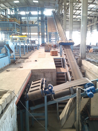
GENERAL DESCRIPTION AND TECHNICAL SPECIFICATION OF BELT CONVEYORS
These specifications apply to belt conveyors incorporating rubber and cotton/nylon fabric belting for handling foundry sand of 90-100 lbs. per cft. density
1. Belt
The conveyor belts will be nylon fabric, 315/3 H. D., grade M-24 or heat resisting quality with 3 mm top and 1.5 mm bottom covers. Heat resisting quality belts will be for conveyors handling knocked out return sand and also for some conveyors handling the hot sand above 80 degree C. the belts will conform to IS-1891, Part-I and Part-II as applicable.
2. Idlers
Load carrying idlers as also return idlers will be 114 mm O. D. idlers. Idler rollers will be made from ERW steel tubes 4 mm shell thickness. The O. D. of the roller will not be machined. The shaft of 20 mm dia. will be of m. s. bright bar. Bearing housing will be of pressed steel design. The rollers will be fitted with SKF 6204 or equivalent deep groove ball bearings and pre-packed with grease for the life of the roller.
Troughing load carrying idlers will be concentric and will have 3 rolls, 20 degree trough Inclination. For conveyors which are partly troughed and partly flat such as distribution conveyors etc. some of the troughing idlers will have 12 degree trough inclination for better control of the belt contour.
One piece design flat carrying idlers will be provided on conveyors where ploughs are used for discharging sand from the conveyor. Return idlers will also be of flat configuration one piece design.
The idler brackets will be fabricated from suitable m. s. sections.
3. Idler Spacing
The load carrying idlers will generally be mounted at a pitch of 1200 mm except in case of loading points where the pitch will be between 350 - 400 mm. In case of belt feeders below storage bunkers, load carrying idlers will be spaced at a pitch of 200-250 mm.
The return idlers will be space at 2400 mm.
4. Drums of Pulleys
The head, tail and snub pulleys will be of mild steel plate welded construction consisting of shell and two end plates on each of which m. s. hub will be welded. The m. s. shaft will be keyed on to hub. The face of the pulleys will be crowned and face length will be 100 mm more than the belt width. The pulley face will be straight approximately for 1/3rd face length in the centre. For the balance portion on both sides of straight length, pulley will have crown. The pulleys will run in externally lubricated self aligning ball bearing plummer block of C. I. construction. The head pulley nominal diameter will be 400 mm and tail pulley nominal diameter 315 mm except otherwise stated. Snub pulleys of 315 mm nominal diameter will be provided for all conveyors having drum centres (distance between head pulley and tail pulley) over 30.0 metres and wherever design demands. The pulleys will be statistically balanced.
5. Head Unit
The head unit will be integral unit consisting of head pulley with its shaft, bearing blocks fitted on m. s. fabricated frame which can be bolted directly to conveyor structure. Pulley with shaft, bearing blocks as well as base frame will be supplied loose for assembly at site.
6. Belt Cleaning Arrangement
A spring loaded type belt scraper will be provided for fitting on the head unit. The rubber strip used with the scraper will be soft rubber 10 mm thick and will be fixed by means of slotted holes to facilitate adjustments, necessitated due to wear.
7. Tail Unit
The tail unit will also be an integral unit consisting of tail pulley with its shaft, screw type tensioning arrangement fitted on a m. s. fabricated frame which can be bolted directly to conveyor structure. Pulley with shaft, screw type tensioning arrangement and frame will be supplied loose for assembly at site.
8. Take-up Device (Tensioning Device)
Screw type take-up device will be provided sufficient to cope with maximum of 2% of belt elongation for all conveyors.
All conveyors above 50.0 meters drum centres will be provided with gravity type take-up arrangement.
9. Drive Unit
The drive motor will be totally enclosed fan cooled squirrel cage induction motor suitable for operation 415 volts, 3 phase, 50 c/s. A.C. supply system. The motor will be continuously rated to comply with IS-325. The motor will be coupled to the head pulley through an oil immersed worm reduction gearbox. Flexible type coupling will be used between motor and reduction gear as well as reduction gear and head pulley except otherwise stated. The drive motor and gearbox will be mounted on a common m.s. fabricated base frame. Sheet metal guards will be provided for the couplings. All the components of drive unit will be supplied loose for assembly at site.
10. Conveyor Frame
The conveyor frame will consist of channel stringers made from ISMC 100 x 50 connected by cross bracing angles. Individual sections of stringers will not generally exceed 5.0 metres length.
11. Conveyor Supports, Platforms and Walkways
Vertical supports to support the conveyor either in the pit (this applies to conveyors running underground below zero level) or from top of the platform (this applies to conveyors running above zero-zero level) will be provided. Platforms and operator’s walkway as required for different conveyors may be provided, if specifically ordered by client. Vertical supports for conveyors will be generally fabricated from m. s. angle sections while the platforms and walkways will be fabricated from m. s. rolled steel sections such as channels, joists, angles etc. operator’s walkway will be 750 mm wide and will be designed for a live load of 500 kgs./sq. m. operator’s walkway will be covered with 5 mm thick O. P. chequered plate. Hand pipes will be shipped in random lengths and fabricated at site. Necessary access ladders to platforms wherever required will be provided. Access ladders will consist of angle/channel stringers with open steel treads 200 mm wide x 600 mm long.
STATIONARY KNOCKOUTS
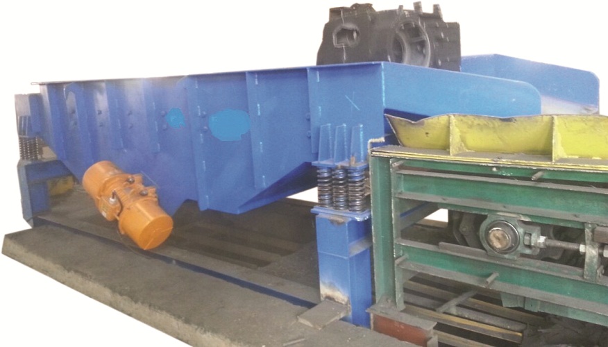
Heavy duty Stationary Knockout Machine are of sturdy construction and easy to maintain. Knockout Grid vibrates at great efficiency which is constant over the entire area and it will give the maximum vibration. The springs are designed in such a way that it will transit very less vibratory effect to the base frame. The Base frames are specially designed to withstand heavy shocks and overloads provided with proper spring rests. The Entire system is driven,Electric vibrating motors. Counter Weights can be adjusted to get the required vibration.Strees Releving process has been made for Traverse.
Product ranges we offer are from 1000 Kgs. to 10000 Kgs. also various deck size available as per requirement.
SELF DISCHARGE SHAKEOUT
Self Discharge Shake-out is intended for separating castings from sand with vibrations. At same time castings are also transported for further process.
Self Discharge Shake-out main parts :
- Vibrating motors
- Shake-out Trough
- Compression Spring
- Traverse
Weights are installed on both shaft ends. Weights orientation are adjustable so that vibrating force and transport speed can be rmodified. Weights are installed in housing and protected against dust.Stress releving process has been done for traverse to ensure the strength on vibrating force.
R-SERIES INTENSIVE SAND MIXER
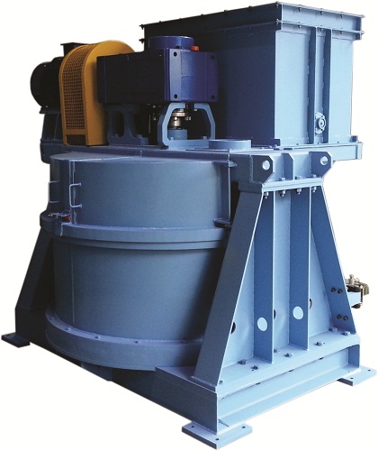
R-SERIES INTENSIVE MIXERS have the following design features to efficiently deliver large volumes of high-quality prepared sand.
- DRIVE UNIT mounted on topof the shell gives easy access for maintenance and less down-time.
- PLANETARY GEARBOX rotates blades at high speed on their own axis and revolves them in pan for thorough mix.
- FLUID COUPLING located between motor and gearbox to protect motor from shock load burnout .
- TRIPLE-ACTION ROTORS each have three arms with replaceable blades with carbide tips for homogenous output of sand.
- INTEGRAL HOPPER built into mixer cover feeds sand and additives into the mixer smoothly and conveniently.
- CENTRAL SPRAYER allows water to be added through central axis via spray heads mounted on rotor arms.
- SIDE WALL SCRAPERS of tungsten carbide continuously clean side walls and push sand towards mixing rotors.
- PNEUMATIC DOOR for bottom discharge with heavy-duty cylinder allows rapid discharge of sand in 12 seconds.
- RUGGED DESIGN with wear-resistant base plate mounted on heavy steel sections for long life.
- PLC CONTROL PANEL operates mixer on full auto cycle and also controls sand, additive and water addition.
CENTRIFUGAL INTENSIVE SAND MIXER
The Centrifugal Intensive Mixer for Green Sand delivers unbeatable reliability, precision, durability and cost-efficient operation. Robust design, precision engineering and quality components combine with the latest process control technology.
- Efficient and economic operation due to high throughput rate and short mixing cycles.
- The large double “S” shaped mixing arms and high capacity blender rotate continuously during loading with pre-batched material and blender rotate in opposite direction, this combination guarantees fast, highly intensive preparation as well as perfect homogenization of the mixing sand.
- Easy access to all wear parts for quick replacement.
- Low maintenance requirement due to robust components and minimum wear of mixing tools and mixer bowl.
- An optional Sand Controller ensures ideal sand quality by enabling integration of dosing, mixing and moistening.An optional precision weighing control system for used sand and additives.
- Specially designed for green sand plant.
- Fully Automated Operation.
